| All of this comes "as is" without any liability or promise. This was pure explorative stuff. I am not an expert. |
Last updated: 31th December 2020
Background
As many people might get Covid-19 simultaniously, there is a chance that medical systems run out of capacity or having enough ventilators.
That happened in the past and might perhaps happen again.
For the vast majority of people Corvid-19 will not be much of a problem, but in worst case scenario having a shitty selfmade ventilator,
that might just run for a few days and perhaps save your live is way better then suddenly not being able to breathe and have nothing at all.
Therefore, like many other people around the globe, i started designing and building a very basic ventilator by myself.
This page informs about it and provides ideas and 3D printing files for download, so you can build things yourself.
Actually i started this project early 2020, but then stopped early may, because the situation heavily improved in germany. As things got a lot more serious end 2020, i finished the last 10% of the project end december.
Apart from that:
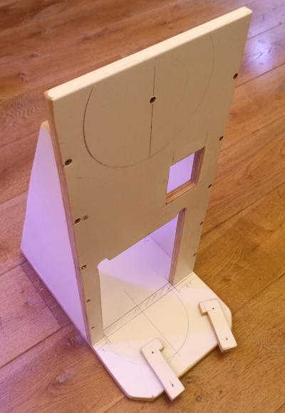
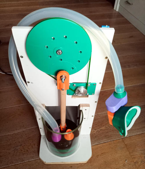
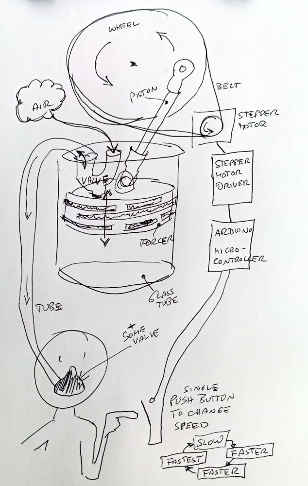
Overall design
My design is based on an Arduino controlled stepper motor powering a forcer within a big glass tube (= spare part for hot dog heaters).
A valve on top of the forcer pumps air into the mask at a speed, that can be changed by a single push button connected to the Arduino.
Tooling
I used the following hard- and software:
| Tool | Description | Needed? | Effort to learn |
| 3D Printer | All models will do and i don't want to advertise products here. One important aspect is the maximum object size, a printer is able to create as one piece. It should idealy be at least something! like 20 x 20 x 20 cm. | 90% yes, as it heavily simplifies building components. Nevertheless you can also build items in a traditional way if you want. | It took me about 2 hours to set it up and learn all the needed basics. These machines are very simple to use. |
| Cura | OpenSource "Slicer" software to transform mesh surfaces of objects from a CAD tool into gcode, that a 3D printer can read to print the object in layers/slices. My printer came with an old version (15.04.6) of it. If yours does also: Do not upgrade. The newest version might be better, but you need to invest a lot of time to understand all that 1000 options. I did not want that and again downgraded to my old and simple, but fully functional version of that software. | If you use a 3D printer: Yes | ~1 hour |
| FreeCAD | OpenSource CAD software | Only if you want to create/modify designs. If you just want to use designs, this is not needed. | I never used CAD before, but with help of some Youtube tutorials and a few tryouts I understood all the needed basics after about a day. |
| Arduino IDE | OpenSource Software (Integrated Development Environment) to program an Arduino microcontroller. I installed the version for Windwos on my PC, but you can also use a web version. | Only if you use an Arduino. | I "used" the IDE for 15 minutes or so. Just to open 2 or 3 examples, save my own code, compile and flash it to the Arduino. This is very simple, as it is made for people who have no or very little knowlede on software development. If you have no idea at all, maybe you need an hour or two to understand the basics (See "Help" > "Getting started"). |
Components
All together the components cost about 200 € or so.
| Item | Description | Images/Videos | Files |
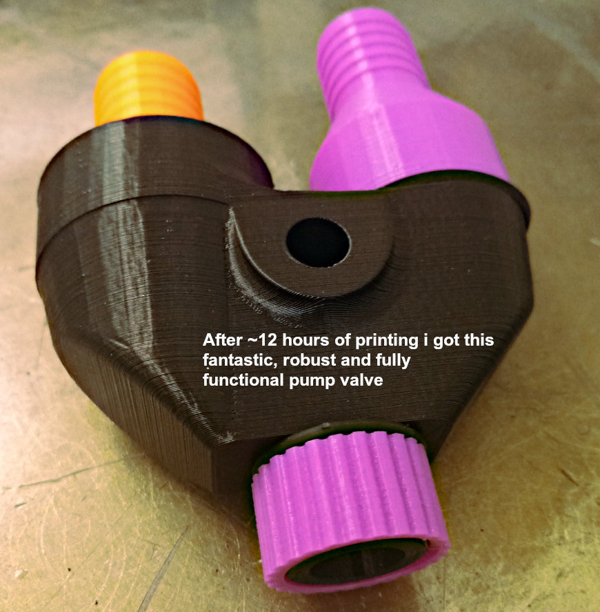
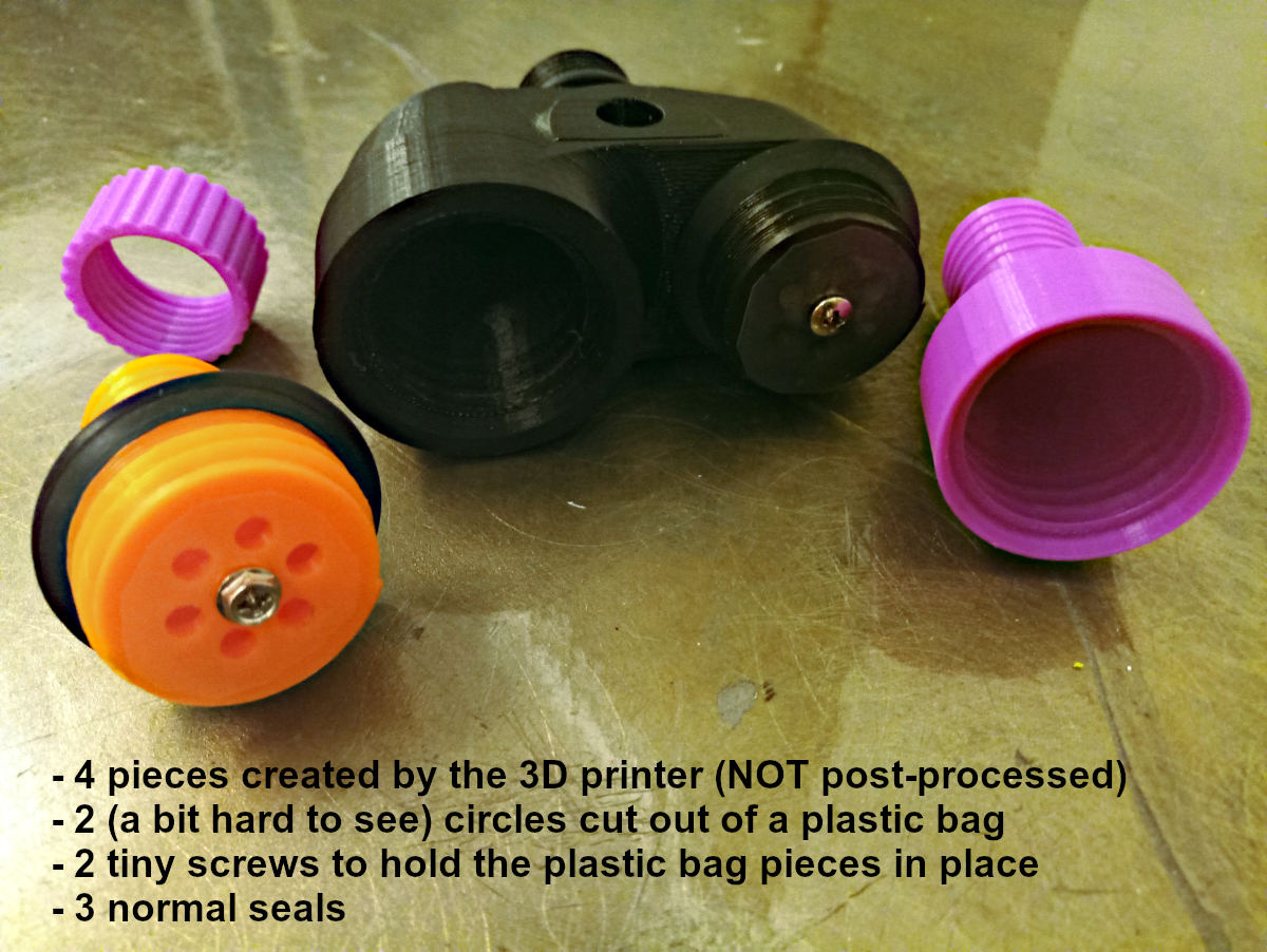
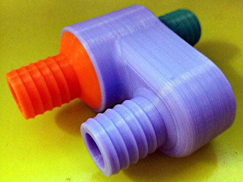
| Pump valve | Two way valve, i found on the internet and use "as is".
The valve sucks air from the first tube and pumps it into the second. This is realized by two small pieces of plastic foil, that seal 6 holes when the airflow goes in one direction.
I plan to screw this valve directly on top of the forcer. As it is designed for that. BTW: It was an amazing experience, that I could physically print out in my Berlin apartment, what pretty clever people from Albuquerque have designed and shared just a few hours ago. |
The designer's video (NOT me)
My self printed copy:
My printer printing (15 MB, 0:27) |
The designer's CAD (NOT mine)
Exported .stl files: |
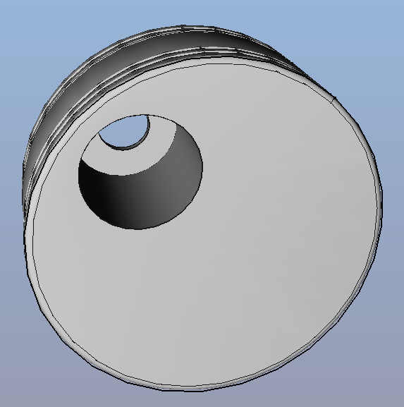
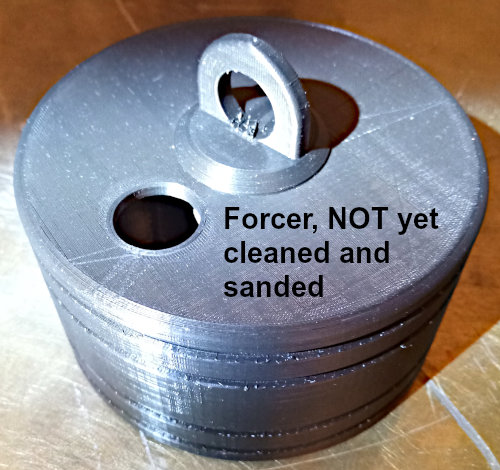
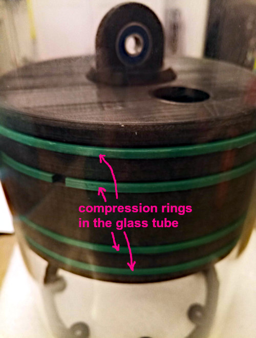
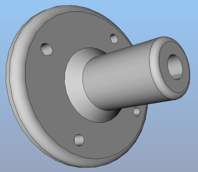
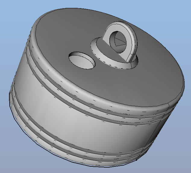
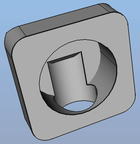
| Forcer | This is my own design and therefore public domain (CC0, No rights reserved).
The forcer's diameter must of course match the cylinder it is supposed to move in.
To seal it, there will be moveable 3D printed compression rings with a slightly bigger diameter, that are placed in the four notches.
The hole on top is for the above pump valve and the vertical hole will hold a ball bearing, so that the piston rod can move it up and down. Note: This is the second CAD drawing I ever made. First was a dummy object to tryout. So if you find a mistake, that might be the reason. I cut rubber from a bicyle tube 4 mm rubber band into each notch and have a compression ring per notch. Maybe multiple segments, so that remaining gaps are closed.
|
FreeCAD file: |
kolben.FCStd (serves as a template for your own geometry)
Exported .stl: |
| Compression rings (and stripes from a bicyle tube) |
I printed four of these.
They need a bit of sanding respectively scraping with a knife to remove the fins.
Then I cut a bicyle tube into 4 mm wide rubber stripes and placed one into each notch. One layer is enough. Make sure the rubber is not folded, but flat on the inner side of the notch.
Rubber bands would also do, but i don't have rubber bands of that size.
The rubber layers softly push the compression rings against the cylinder. Not exactly 100%, but all four together almost perfectly seal it with very little friction.
Make sure to print the compression rings solid.
|
|

FreeCAD file: |
compressionring.FCStd (serves as a template for your own geometry)
Exported .stl: |
| Cylinder | I use a glass tube of 15 cm inner diameter, 21.5 cm height and 5 mm thickness, that is originally intended and sold as a hotdog heather replacement part. Glass has minimal friction, but a big plastic tube might also work. |

|
|
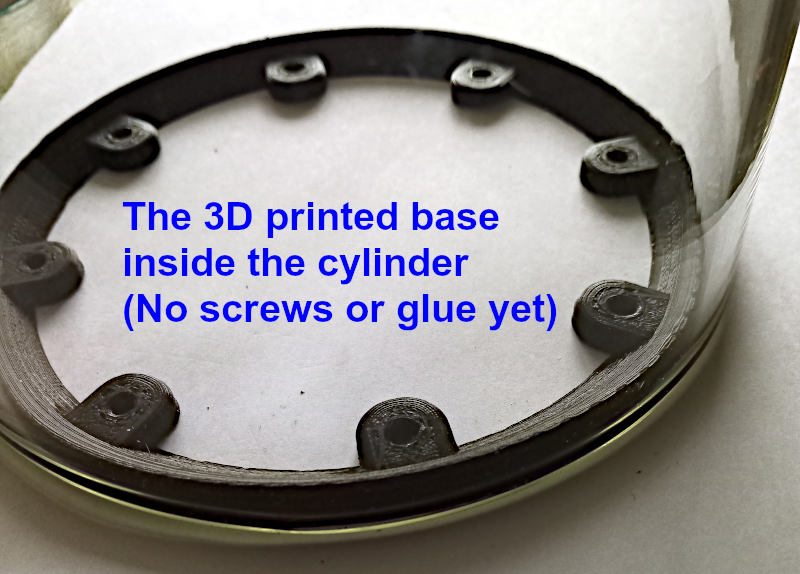
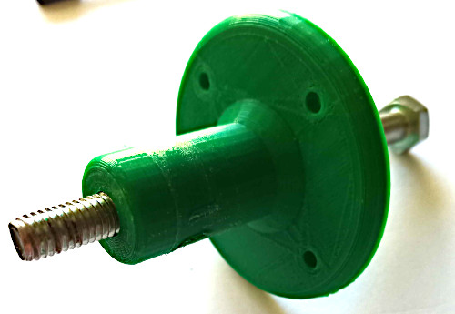
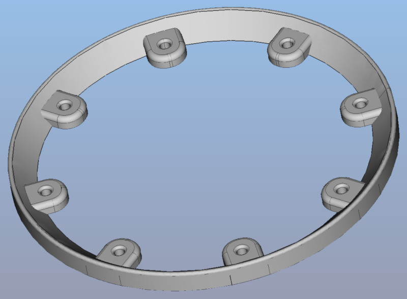
| Cylinder base | To mount the bottom of the cylinder (glass tube) to a plywood board, i will use a circle with some holes for screws. This is my own design and therefore public domain (CC0, No rights reserved). The circle (149 mm outer diameter) fits into the cylinder and has a height of ~1 cm. I will screw that base onto the board and glue the cylinder onto/around it with silicone or silicone glue. Both should work and also fully seal the bottom. In case increased stability will be needed, that can easily be achieved by 3 or 4 pieces of wood, that get glued around the cylinder to hold it in place. |
|
FreeCAD file: base.FCStd (serves as a template for your own geometry)
Exported .stl: |
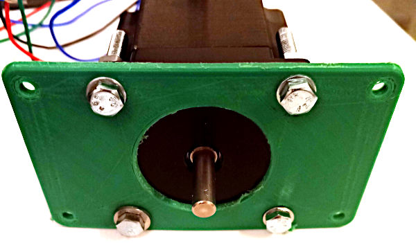
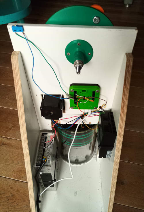
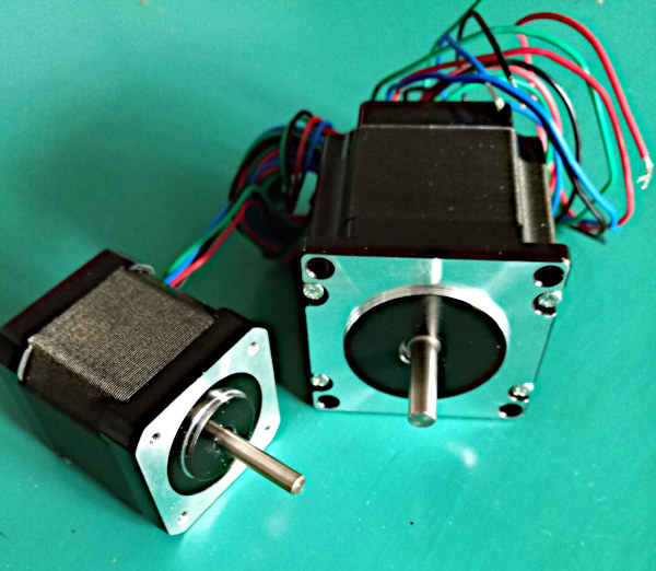
| Stepper motor | I bought a "Nema 23" with 1,26 Nm. That's the one on the right. I assume, there is not much power needed to pump 0.5-1 liter of air into a lung. In emergency situations, this is normally done using an Ambu bag, where one hand squeezes the bag. And as finger muscles are not that powerful i think the motor for a ventilator can also be quite small. So maybe the smaller motor on the left (a "Nema 17") would also be sufficient, but i don't want to try that out. |
|
|
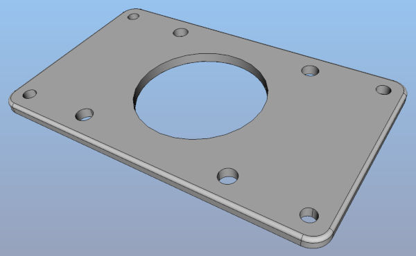
| Stepper motor mount | The motor drives a belt, which needs to be tight. This 3 mm board with the stepper motor in the middle can easily be moved to the right position and then screwed to the plywood board. |
|
FreeCAD file: mount.FCStd (serves as a template for your own geometry)
Exported .stl: |
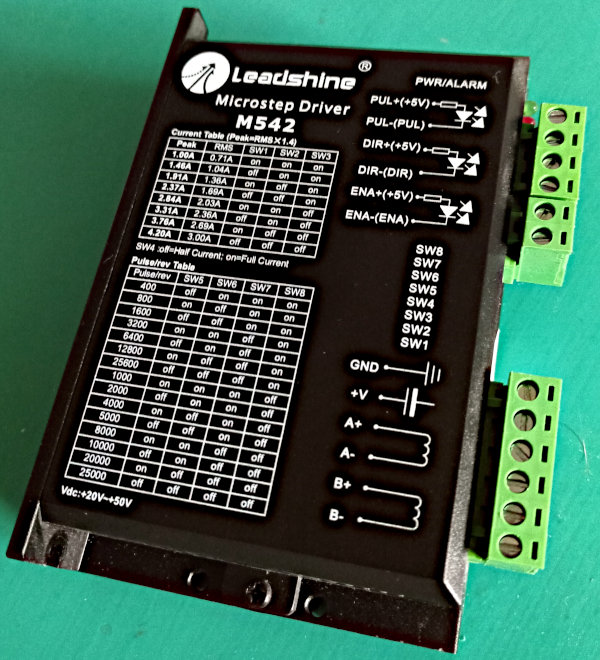
| Stepper motor driver | I have old powerful ones for my CNC machine, that i replaced a while ago. I will use this big stepper driver, so that it can drive the big stepper motor (a "Nema 23") above. Like in that Youtube video linked on the right, that i found after searching for about 10 seconds. |
|
Instruction video (Not mine) |
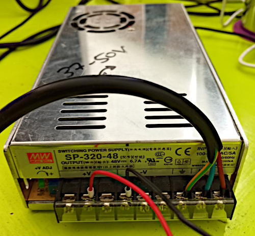
| Stepper motor power supply | I have a box with maybe 50 old power adapters of all sizes. The stepper motor needs 2.8 Ampere, but my (oversized) Stepper motor driver needs 20 - 50 volt. So i use this old power adapter, i had in my CNC machine a few years ago. That works (37 Volts), but is really heavily oversized. You could go with a smaller Stepper motor driver and a normal 12 Volt power adapter. Alternatively I could simply go with two normal 12 Volt adapters in serial, so I get 24 Volt out of it. |
|
|
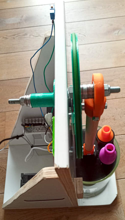
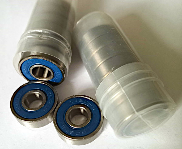
| Ball bearings | I bought some bearings for inline skates. M8, 22 mm outer diameter, 7 mm thick. |
|
|
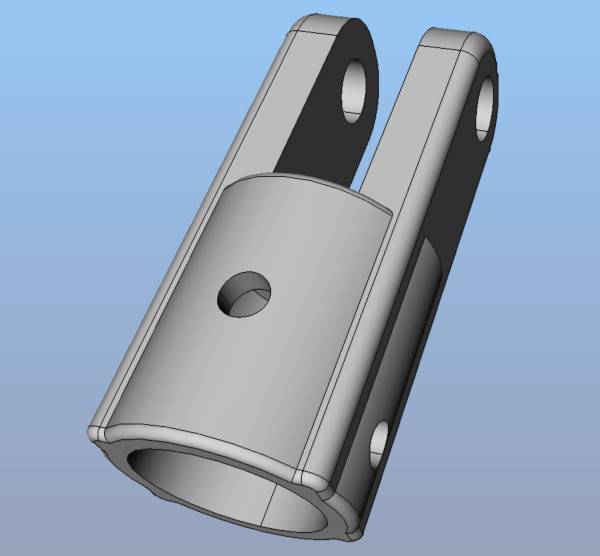
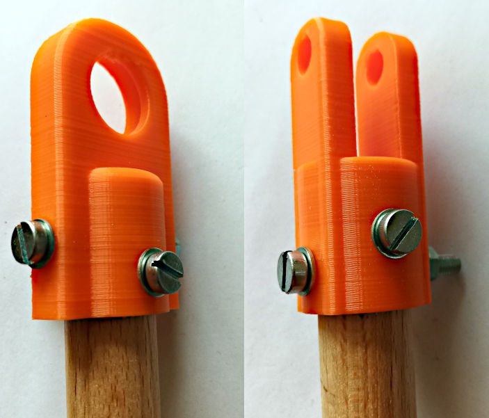
| Piston rod end connectors |
My own designs are again public domain, CC0.
As piston rod i will use a round timber with 2 cm diameter, that gets fixed to the connectors with two M5 screws on each side. The connector on the upper side (to the big wheel) is slightly asymetrical on purpose, so that the ball bearing can not fall out. |

|
FreeCAD files: Upper one: pistoncon2.FCStd Lower one: pistoncon1.FCStd (serve as a template for your own geometry)
Exported .stl: |
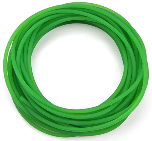
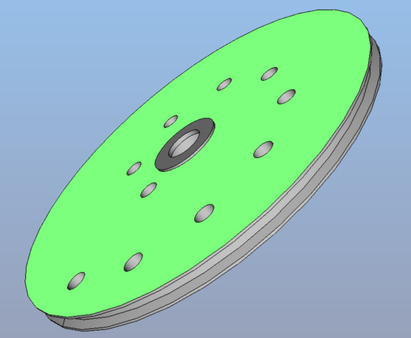
| Gear transmission parts |
I just bought a wheel, that fits the bigger stepper motor's axis, that can drive a round Polyurethane (PU) belt between 3 and 5 mm. As belt i bought one with 4mm diameter, that's 10 m long. So it has to be cut to size (maybe 50 cm) and to be connected to a circle. That connection can be done manually by heating up the end faces to 300 degree celsius for about 10 seconds, pressing the ends together (using 3 metal L profiles should help positioning), letting them cool down for 5 minutes, cutting away the melted outer material and cooling it down for another 20 minutes. For that you normally need a machine, that heats up to a precise temperature, but i guess some piece of metal heated up to 300 degree in my oven will do the same job. It was actually fun to see, that my oven can heat up to exactly 300 degrees. That's a sign, i guess : )
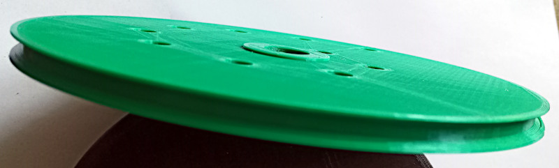
The big wheel (my own design, therefore public domain, CC0) has many options, where to mount the piston rod. Depending on the hole's position, the volume of pumped air varies. To simplify mounting an axis (long M8 screw) for the big wheel, i designed and printed a screw holder, that is to be mounted on the opposite side of the plywood board. This is an optional part, that keeps the axis vertical to the board. |

|
FreeCAD files: bigwheel.FCStd screwholder.FCStd (serve as a template for your own geometry)
Exported .stl: |
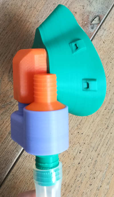
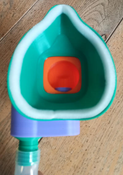
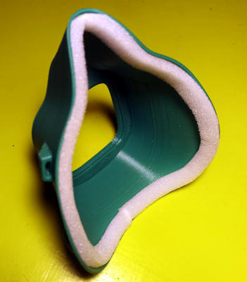
| Mask | I bought a standard CPR mask, but then decided to self print an open source one from the internet, as it is easier to glue an adaper to it and it actually better fits my face. There are meanwhile a lot of files for all kind of masks available for download. I use the open source mask linked on the right. To better seal it I put a stripe of foamed material on the inside. These adhesive stripes are normally used to seal windows. |
|
Link to the mask i used
|
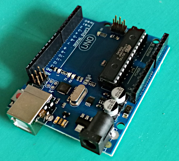
| Microcontroller |
I bought an Arduino UNO.
The software will control the stepper motor, so that the speed can be changed by a single push button.
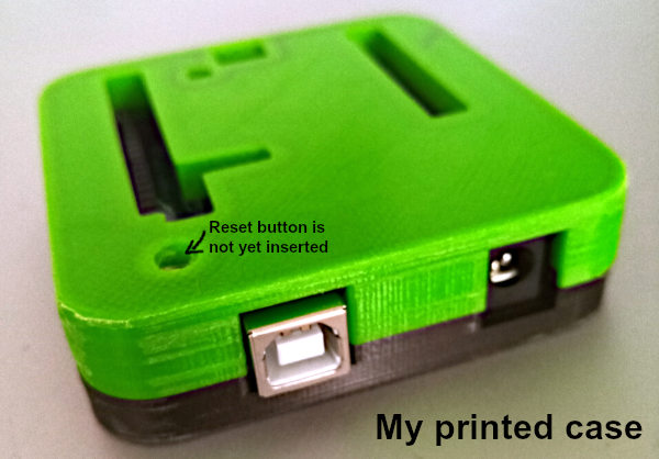
A case for an Arduino can of course easily be downloaded and printed. Note: A simple pulse generator made out of electronic components for a few cents would also do the job. Using a microcontroller to simply generate pulses is a massive overhead, but it's more fun and so i use one here : ) |
|
Link to Arduino page with tutorials, examples etc. |
| Software | As expected, this is just a few trivial lines. My file (public domain, CC0) is linked on the right. Note, that the conrete values for changing speed need adjustment when the machine is assembled. | Ventilator.ino | |
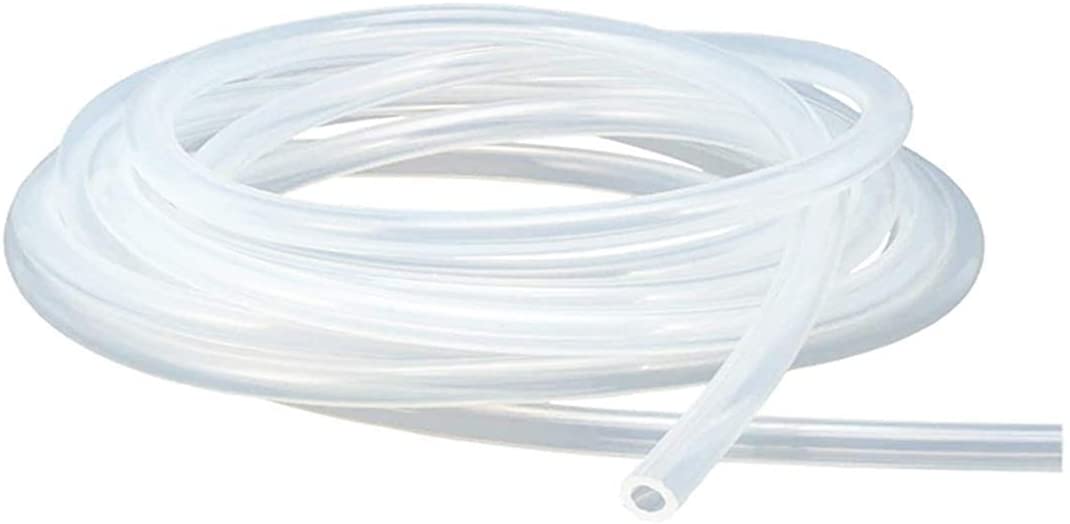
| Tube | I bought a 2 meter long silicone tube with 19 mm inner and 25 mm outer diameter. |
|
|
| Plywood | I have a lot of old 15 mm plywood boards in my basement, so I simply used those. | ||
| Diversion valve |
A valve that switches at the patient/mask side. Again that guy from Albuquerque, who created the pump valve above, had already created one and I only needed to print it out. That's amazing.
The designer's video (NOT me) |
My printed copy:
The designer's CAD (NOT mine) |
Exported .stl files: |
| Adapter | My own design is again public domain, CC0. I created this little connector, that fits onto! my printed mask. The valve can therewith be glued! directly onto the mask. |
|
FreeCAD files adapter.FCStd (serves as a template for your own geometry)
Exported .stl: |
Assembly / Integration
| Area | Description | Images/Videos | Files |
| Software |
Important: As i (by oversight) use a normally closed contact (NCC) as a push button, you might need to modify the software if you use a normally open contact (NOC)
or if you want different speeds. This is a bit of tryout, but it's very simple. Here is how to transfer the software into the Arduino:
|
Arduino IDE | |
| Electrical |
Here is how to connect these compnents (others will of course also do):
|
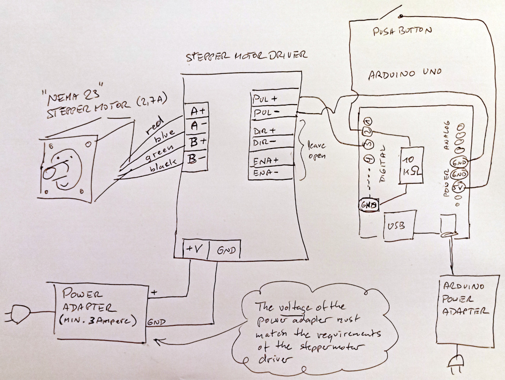
Good instruction video (NOT mine) |
|
| Mechanics |
The assembly is pretty much self explaining when you see the pictures or the video below. The following are just notes or aspects to consider:
|
||
User Guide
Plug in the two power adapters. Put on the mask. Push the pushbutton a few times to select the right breathing speed. That's it.
But note: As the valve on the mask side uses gravity, you must sit upright. The diversion valve will not work in the horizontal.
>>> Video of the machine pumping air <<< (.avi, 9 MB)
My own exploration stopped at this point. I don't expect to ever use the machine, so I will likely not finetune anything. What's additionally needed is two (upscaled) L connectors like this to place in the tube. Maybe 20 cm from each side. Othwerwise the tube is easily folding. If you proceed or actually use a machine like this, please let me know.
Contact
In case you have questions, advice or whatsoever ideas: Feel free to contact me.
Wolfgang Smidt, Berlin, Germany,
wuff@worldwidewolf.de
Some links to my other pages, that are all entirely offtopic and in german:
Landing page
Main page
Blog